UART Glitch of Arduino
The Bus Pirate can be used to trigger glitching attacks based on UART serial timing:
- Power glitching
- EMP “blasting”
- Clock glitching
For this demo, the Bus Pirate will be used to trigger a power glitching attack against an Arduino Uno. The Arduino’s software has a UART that is used to enter a password; this password will by bypassed by a power glitch. A custom circuit on a Bus Pirate Blank Plank is used to perform the actual power glitch against the Arduino.
The Bus Pirate is used to time and trigger the “glitching” activity; actual external electrical interface to the target and/or glitching tool is required. This may be in the form of a separate device, custom plank, breadboarding, or circuit board.
Get Bus Pirate & Accessories
Connections
| Bus Pirate | Target/Interface | Description |
|---|---|---|
| TX-> | Arduino pin 0 (RX) | Serial UART from Bus Pirate to Arduino |
| RX<- | Arduino pin 1 (TX) | Serial UART from Arduino to Bus Pirate |
| Vout/Vref | Arduino 5V | 5volt power supply |
| GND | Arduino GND | Ground |
Don’t enable Bus Pirate power supply; the I/O buffers are powered by the Arduino.
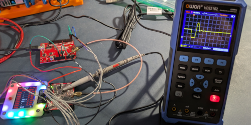
See it in action
Glitching Background
Setting up a glitching attack can be complicated and involve many factors. The UART Glitch command is a specific type of glitch attack using UART timing to trigger the attack.
Consider this case:
- Target device (the Arduino, in this case) has a UART interface
- This interface can access important functionality in the target, and is therefore password protected
Normal usage would be:
- User connects to the UART interface with some terminal device, for example a Bus Pirate in UART mode with the bridge command
- User is prompted to enter the password
- User enters incorrect password and is re-prompted
- User enters correct password and gains access to the command line environment
Internally to the target, the code is most likely accepting the user’s input over UART, adding each newly-entered character to a buffer and waiting for a return character (user hits the ENTER button). Then the code will use some method to compare the user’s entry to the “good” password to decide if the user gets access.
From a defensive programming/security standpoint, the user should only be allowed a fixed number of failed attempts and there should be a delay after a failed attempt. Also, the time between the user hitting ENTER and the code checking the password should not be constant; there should be variation each pass to prevent the kind of timing used in glitching.
The Arduino code used in the target for this demo does none of those things, and is in fact lifted from a very common consumer IoT device.
To try to bypass or glitch the password authentication routine, the power glitching attack will “short” the voltage to the Arduino’s microcontroller for a very short period. The duration and timing of this attack is crucial to success.
Timing the Attack
The first step would be to use a logic analyzer to determine if the timing between the user sending a return on a bad password attempt and the target sending the next prompt is constant (or at least has little variation). The easiest way to do this is to use a logic analyzer on the TX and RX lines and measuring the time:
The Bus Pirate has a follow along logic analyzer built in that can be used for this.
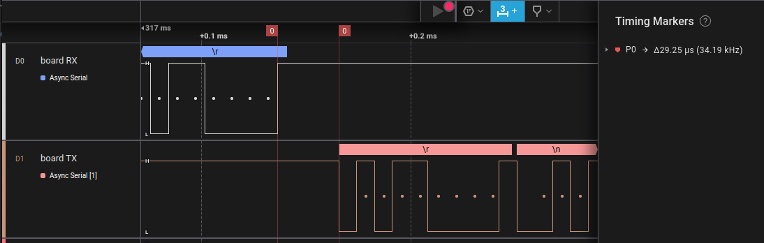
In the above trace, the timing between the end of the user’s input (top trace), and the target sending the prompt to try again is 29.25 microseconds. Doing this test many times showed that this timing was pretty constant.
Knowing this, it is reasonable to guess that the password validation routine is happening some time between 10 and 20 microseconds after the user’s attempt is received by the target.
The only way to know for sure is through experimentation, but the logic analyzer has narrowed the timing down.
Attack Hardware
The Glitch command will activate Bus Pirate IO0 during the attack; that output will turn on for a very short time when triggered. It is implementation dependent to make use of this.
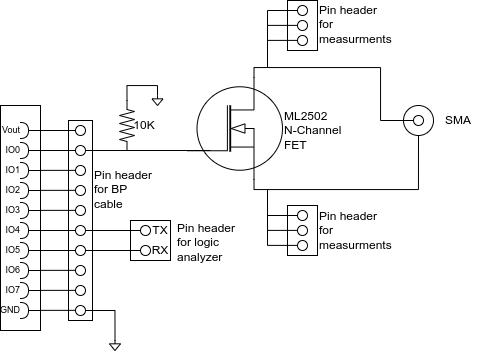
In this case, a custom Blank Plank is used to do the power glitching. Here is the schematic:
The actual plank: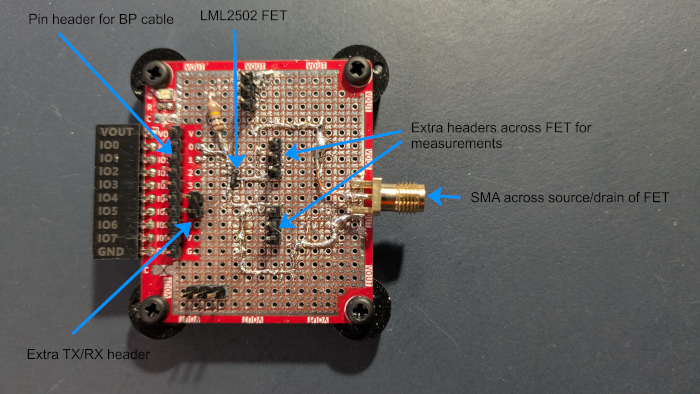
The way it works is that the FET will fire when the Bus Pirate triggers the glitch. The Target (Arduino, in this case) is connected across the FET via the SMA connector. At the Arduino side, the connection is directly across the VCC and GND pins of the AVR microcontroller.
It is essential that the connection is as close to the microcontroller pins as possible. For the demo, the connection was made directly to the MCU pins: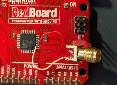
Glitching Attack Sequence
In operation, the glitching attack sequence goes like this:
- Wait for the glitch ready input
IO1. This allows external devices to be ready; this step can be disabled by configuration if not necessary. For example, if doing EMP blast glitching, it may be necessary to wait for the EMP device to be ready - Send the “password enter” character from Bus Pirate to target over UART. This is configurable, typically a
returnornewlinecharacter - Wait for a configured delay. This is time is based on the timing obtained from the logic analyzer
- Turn on the glitch trigger output
IO0. Leave the output on for the configured time, then turn it back off. This is typically a very short time when power glitching - Read the UART characters coming back from the target. Parse the return string, looking for a particular character as an indication of success. For example, if the target responds with “Please enter password”, the presence of the the letter “P” is an indication the glitch failed. This character is configurable.
- Wait an additional delay to allow components to cool, EMP blaster to recharge, etc.
- If the glitch did not succeed, start at the beginning.
Setup
The configuration can be set based on the approximate timing from the logic analyzer trace:
HiZ> m uart

Mode: UART

Use previous settings?
UART speed: 115200 baud
Data bits: 8
Parity: None
Stop bits: 1
Hardware flow control: None
Signal inversion: Non-inverted (Standard)

y/n, x to exit (Y) >

Actual speed: 115207 baud
UART> glitch

Use previous settings?
Glitch trigger character: 13 (ASCII)
Glitch trigger delay: 1400 ns*10
Glitch vary time: 3 ns*10
Glitch output on time: 7 ns*10
Glitch cycle delay: 100 ms
Normal response character: 80 (ASCII)
Number of glitch attempts: 1000
Bypass 'READY' input checking: Bypass enabled ('READY' check disabled)

y/n, x to exit (Y) >

UART>
- use the
mcommand to selectuartmode - configure UART to match the target’s UART baudrate, character size, etc.
- use the
glitchcommand to configure or start glitching:Glitch trigger character- this is the ASCII value of the character to send to the target to begin the process. Typically character 13, thereturncharacterGlitch trigger delay- the amount of time after the end of the sending the trigger character before turning on the glitch output. This value is in terms of nanoseconds * 10; so an entry of 1400 is 14,000 nanoseconds or 14 microsecondsGlitch vary time- this allows some variation on timing. If the value is 3, the first glitch delay will be 14.00 microseconds, then the next at 14.03 microseconds, 14.06, etc. for 5 sequences. The the glitch time will reset to theGlitch trigger delayGlitch output on time- how long to turn the output on. This is also in nanoseconds * 10, so a value of 7 is 70 nanoseconds, .070 microseconds.Glitch cycle delay- a fixed amount of time to wait between cycles; this value is in millisecondsNormal response character- the ASCII value of a character that would normally be seen if the target did not glitch; what the user would normally see if the password entered was not correct. If the target responds with “Please enter password” for a bad password attempt, a good value would beP- ASCII 80Number of glitch attempts- the number of tries before giving up. Note that the actual number of attempts will be 5 times this number, allowing for glitch time variationBypass 'READY' input checking- by default, the glitcher will wait until inputIO1is “high” before starting each glitch sequence. This is used to make sure the glitching hardware is ready. If there is no need to check for “ready”, set this value to1to disable the check.
Perform the Glitch Attack
Start by enabling UART mode, the using the bridge command to verify communications:
HiZ> m uart

Mode: UART

Use previous settings?
UART speed: 115200 baud
Data bits: 8
Parity: None
Stop bits: 1
Hardware flow control: None
Signal inversion: Non-inverted (Standard)

y/n, x to exit (Y) >

Actual speed: 115207 baud
UART> bridge
UART bridge. Press Bus Pirate button to exit.
************************************
Test glitch target (victim), v 0.9
************************************
### Please enter password ###

*****
### Please enter password ###


### Please enter password ###


UART>
The
bridge command shows that the target is accepting passwords, and returns ### Please enter password ### when the wrong password is entered. Use the Bus Pirate button to exit bridge mode.Next, enter the glitch command, configure it, and it will begin running:
UART> glitch

Use previous settings?
Glitch trigger character: 13 (ASCII)
Glitch trigger delay: 1400 ns*10
Glitch vary time: 3 ns*10
Glitch output on time: 7 ns*10
Glitch cycle delay: 100 ms
Normal response character: 80 (ASCII)
Number of glitch attempts: 100
Bypass 'READY' input checking: Bypass enabled ('READY' check disabled)

y/n, x to exit (Y) >

UART glitching.  Press Bus Pirate button to exit.
Attempt   1, delay 14000ns RX: ### Please enter pa
Attempt   1, delay 14010ns RX: $>
Target glitch success!

UART>
It appears the glitch was successful on the second attempt. Instead of returning
### Please enter password ### over the UART, the target returned $>.As a final verification, use the bridge command again to explore the changes in the UART connection:
UART> bridge
UART bridge. Press Bus Pirate button to exit.
$>
$> help
This is just a small example, there really isn't any kind of command
processing.  Only commands are 'help', 'reboot', and 'info.
$> info
Target info:
'consoleEnabled': true
$>
The Arduino code in the target just provides this basic interface; of course a “real” target could have much more functionality.
Final Notes
Glitching attacks are notoriously difficult. It takes many, many attempts to get the timing correct, and even then may not be very repeatable. The glitch command in the Bus Pirate is a useful learning tool to begin to experiment with the concept and process of glitching. It should be flexible enough to be used on a variety of targets.
The Arduino code for the example target is fairly simplistic, and is full of bad coding and poor security practice. As noted above, this code was lifted almost exactly from a popular consumer IoT device and is similar to what might be found in the wild.
Click here to expand Arduino target source code
/******************************************************
* sample code to exercise glitching a 328p
*
* After powering up, the code will put out a short
* identifier, then start asking for a password. (over UART)
*
* User can try as many times as they want, there is
* no limit.
*
* If correct password is entered, the user will get a
* "$>" prompt.
*
* The goal is the inject a power or other fault just
* as the password is being checked and thereby bypass
* password checking.
*******************************************************/

#define MAX_PWD_LEN 32
#define CONSOLE_BUFFER_LEN 64

static const char* PASSWORD = "myP4ssw0rd";
static bool consoleEnabled = false;

char consoleBuffer[CONSOLE_BUFFER_LEN] = {'\0'};

int simpleCLILoop(const char* prompt);
int readCommandFromUART(const char* prompt);

void setup() {
  Serial.begin(115200);
  Serial.println("************************************\r\n Test glitch target (victim), v 0.9\r\n************************************");
}

void loop() {
  // put your main code here, to run repeatedly:
  simpleCLILoop("$> ");
}


/******************************************
* This method is called continually to get
* user interactivity over UART.  If the
* password has not yet been entered, this
* method will continually poll for it
* until it is found.
*
* This method may seem strange, and even
* a bit contrived, but it is something that
* I pulled almost exactly from a consumer
* IoT device.
*
* Yes, there is a stack-based buffer overflow
* here (and is in the actual device out in
* the world, too.)
******************************************/
int simpleCLILoop(const char* prompt) {

  char password[MAX_PWD_LEN] = {'\0'};
  uint8_t pwdInx;
  int readChar;
  int compareResult;

  // if password has been entered (consoleEnabled == true), then
  // skip this whole block.  Otherwise keep trying until correct
  // password has been entered.
  while (!consoleEnabled) {
    Serial.println("### Please enter password ###\r\n");  // prompt user
    pwdInx = 0;  // entered password character counter

    // loop runs continuously until <RETURN> key pressed
    while (true) {
      if (Serial.available() > 0) {     // wait for UART rx
        readChar = Serial.read();       // get that char
        readChar &= 0xff;               // mask off lower 8 bits

        if (readChar == '\r') {         // user hit <RETURN>
          break;                        // so break out of forever while() loop
        } else if (readChar == '\b') {  // user hit <BACKSPACE>
          if (pwdInx > 0) {             // if at least one char has been entered
            --pwdInx;                   // decrement entered password char count
            Serial.print("\b \b");      // send backspace, space, backspace over UART
          }                             // to clear the last '*'
        } else {                        // not <RETURN> or <BACKSPACE>
          password[pwdInx] = readChar;  // append the this char to the user's password entry
          ++pwdInx;                     // increment the entered password char count
          Serial.print('*');            // print out an asterix
        } // testing entered UART char
      } // waiting for UART char
    } // main while() loop

    password[pwdInx] = '\0';            // null terminate user entered password

    // compare user entry to "good" password
    compareResult = strcmp(PASSWORD, password);

    if (!compareResult) {
      consoleEnabled = true;            // set bit to indicate password is good!
    }

    Serial.println("");                 // print out a newline
  } // while (!consoleEnabled)

  *consoleBuffer = '\0';
  return (readCommandFromUART(prompt));
}


/******************************************
*                                         *
******************************************/
int readCommandFromUART(const char* prompt) {
  bool enterd = false;
  int readChar = 0;
  int readInx = 0;

  Serial.print(prompt);

  while (!enterd) {
    if (Serial.available() > 0) {
      readChar = Serial.read();
      readChar &= 0xff;

      if (readChar == '\r') {
        break;
      } else if (readChar == '\b') {
        if (readInx > 0) {
          --readInx;
          Serial.print("\b \b");
        }
      } else {
        consoleBuffer[readInx] = readChar;
        ++readInx;
        Serial.print((char)readChar);

        // dont allow a buffer overflow here
        if (readInx == (CONSOLE_BUFFER_LEN - 1)) {
          break;
        }
      }
    }
  }

  consoleBuffer[readInx] = '\0';
  Serial.println("");

  if (strlen(consoleBuffer)) {
    if (!strcmp("info", consoleBuffer)) {
      Serial.println("Target info:");
      Serial.print("\t'consoleEnabled': ");
      (consoleEnabled) ? Serial.println("true") : Serial.println("false");
    } else if (!strcmp("help", consoleBuffer)) {
      Serial.println("\tThis is just a small example, there really isn't any kind of command");
      Serial.println("\tprocessing.  Only commands are 'help', 'reboot', and 'info.");
    } else if (!strcmp("reboot", consoleBuffer)) {
      // kind of a sledgehammer - jump to the reset vector to reboot.
      asm("jmp 0");
    } else {
      Serial.print("'");
      Serial.print(consoleBuffer);
      Serial.println("' isn't a supported command.");
    }
  }

  return (strlen(consoleBuffer));
}
Get a Bus Pirate
Get Bus Pirate & Accessories
- Browse Complete Bus Pirate hardware collection
- Bus Pirate 5 REV10 with enclosure
- Probe Cable Kit
- Auxiliary Cable Kit
- Quick Connect Adapter